An object is 20cmto the left of a thin diverging lens that has a 30cmfocal length. (a) What is the image distance i? (b) Draw a ray diagram showing the image position.

Short Answer

Expert verified
  1. The image distance i is -12cm.
  2. The ray diagram is drawn showing the image position.

Step by step solution

01

Listing the given quantities

Object distance p=20cm

Focal length of the lens f = -30cm

02

Understanding the concepts of lens equation

Here, we need to use the equation of a lens to calculate the image distance for a diverging lens.

We can draw a ray diagram showing the image position using two rays, the ray passing through the center of lens and other ray passing parallel to the principle axis.

Formula:

1p+1i=1f

03

Calculations of the image distance

(a)

The lens equation relates an object distance p, lens focal length f and the image distance i as

1p+1i=1f1i=1f-1p1i=p-ffpi=pfp-f=(20cm)(-30cm)(20cm--30cm)=-12cm

The negative sign shows that the image isvirtualand to the left side of the lens.

The image distance i is -12cm.

04

Step 4: The ray diagram showing the image position

Unlock Step-by-Step Solutions & Ace Your Exams!

  • Full Textbook Solutions

    Get detailed explanations and key concepts

  • Unlimited Al creation

    Al flashcards, explanations, exams and more...

  • Ads-free access

    To over 500 millions flashcards

  • Money-back guarantee

    We refund you if you fail your exam.

Over 30 million students worldwide already upgrade their learning with Vaia!

One App. One Place for Learning.

All the tools & learning materials you need for study success - in one app.

Get started for free

Most popular questions from this chapter

An object is placed against the center of a thin lens and then moved away from it along the central axis as the image distance is measured. Figure 34-41 gives i versus object distance p out to ps=60cm. What is the image distancewhen p=100cm?

In Fig. 34-38, a beam of parallel light rays from a laser is incident on a solid transparent sphere of an index of refraction n. (a) If a point image is produced at the back of the sphere, what is the index of refraction of the sphere? (b) What index of refraction, if any, will produce a point image at the center of the sphere?

9, 11, 13 Spherical mirrors. Object Ostands on the central axis of a spherical mirror. For this situation, each problem in Table 34-3 gives object distance ps (centimeters), the type of mirror, and then the distance (centimeters, without proper sign) between the focal point and the mirror. Find (a) the radius of curvature r (including sign), (b) the image distance i, and (c) the lateral magnification m. Also, determine whether the image is (d) real (R) or virtual (V), (e) inverted (I) from objectO or non-inverted (NI), and (f) on the same side of the mirror asO or on the opposite side.

In Fig. 34-51, a box is somewhere at the left, on the central axis of the thin converging lens. The image Imof the box produced by the plane mirror is 4.00cm “inside” the mirror. The lens–mirror separation is 10.0cm, and the focal length of the lens is 2.00cm. (a) What is the distance between the box and the lens? Light reflected by the mirror travels back through the lens, which produces a final image of the box. (b) What is the distance between the lens and that final image?

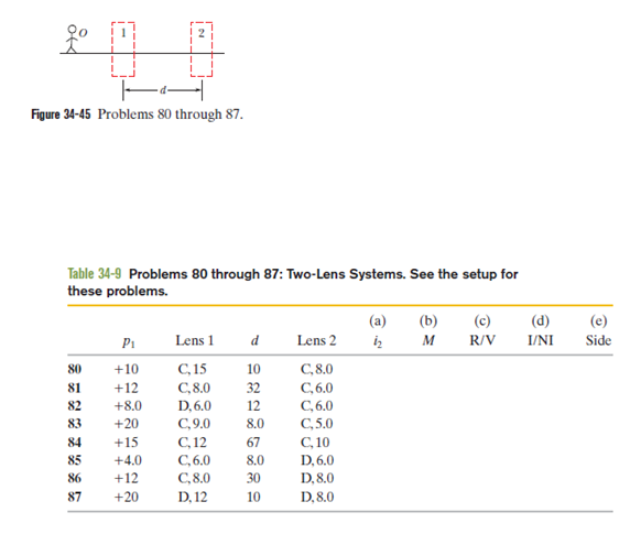
80, 87 83 Two-lens systems. In Fig. 34-45, stick figure O (the object) stands on the common central axis of two thin, symmetric lenses, which are mounted in the boxed regions. Lens 1 is mounted within the boxed region closer to O, which is at object distance p1. Lens 2 is mounted within the farther boxed region, at distanced. Each problem in Table 34-9 refers to a different combination of lenses and different values for distances, which are given in centimeters. The type of lens is indicated by C for converging and D for diverging; the number after C or D is the distance between a lens and either of its focal points (the proper sign of the focal distance is not indicated).Find (a) the image distancei2for the image produced by lens 2 (the final image produced by the system) and (b) the overall lateral magnificationMfor the system, including signs. Also, determine whether the final image is (c) real(R)or virtual(V), (d) inverted(I)from object O or non-inverted(NI), and (e) on the same side of lens 2 as object O or on the opposite side.
See all solutions

Recommended explanations on Physics Textbooks

View all explanations

What do you think about this solution?

We value your feedback to improve our textbook solutions.

Study anywhere. Anytime. Across all devices.

Sign-up for free